-Overview
-MODBUS Frames: ADUs and PDUs
-ADU Fields
-PDU Fields
-MODBUS Addresses
-Most Frequent Operation or Function Codes
MODBUS specifies the procedure that the client and server use to exchange data, the format of this data, how errors are handled, etc. It does not strictly specify the type of communications network to be used, so it can be implemented on networks based on Ethernet, RS-485, RS-232 etc.
This document explains the MODBUS specification in a general way, without going into much detail in some of its particularities, however its content must be more than sufficient for those who wish to understand the general operation of this standard. On the other hand, anyone who wants to carry out a precise implementation of MODBUS must refer to the documentation available on modbus.org or to the specific documentation of the manufacturer of the equipment with which he or she is going to communicate.

Communication from the client to the servers can be of two types:
- “peer to peer”: in which 1:1 communication is established from the "client to a server", the client requests information and the server responds (the command is sent to a device between the 1d and 247d addresses). It is the type normally used.
- “broadcast”: in which 1:n communication is established from the "client to all servers", the client sends a command to all the servers in the network without waiting for a response (it is sent to the @0d address).
The basic sequence in MODBUS communications always consists of a question frame on the part of the client, followed by its corresponding response frame on the part of the server consulted:
- Question (request): the client sends the function code that tells the server what operation to perform, and the bytes necessary (data, verification...) for its execution.
- Response: The server responds with the confirmation or data resulting from the execution of the function.
There are some specific cases where there is more than one answer frame for a question frame, such as when the client requests the execution of an operation whose response may take the server some time to elaborate. In these situations, the server sends a first response indicating that it does not yet have the data and it will take some time to have it, and a second one with the data or confirmation of the operation..
MODBUS does not prevent a computer acting as a server from acting as a client with other devices and vice versa if the network type allows it. This can be useful in applications that require bidirectional data exchange.

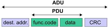
- PDU: Protocol Data Unit: it is common to all MODBUS implementations. The structure and data of this part is the same regardless of the lower layers of communications.
- ADU: Application Data Unit: these are data that accompany and encapsulate the PDU and can be different depending on the particularities of the lower layers of communications.
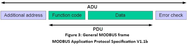
The fields in the ADU are different depending on the type of MODBUS implementation. The most widespread implementations of MODBUS are: MODBUS TCP, MODBUS RTU and MODBUS ASCII. On the other hand, the PDU fields are always the same: Function Code + Data. The content of the Data field will depend on the Function Code, as each operation requires different data to execute.
Within the same MODBUS implementation, the ADU fields are always the same, both in the question frame and in the answer frame, while the PDU fields can be different because in one case they contain the request information and in the other the response data.
ASCII MODBUS frames (text format):
-ADU: Start of frame: 1 byte encoding the ASCII character ":" (0x3A)
-ADU: Server No.: 2 bytes corresponding to the 2 ASCII characters with the hexadecimal representation of the address of the target server of the frame.
-PDU: Operation code: 2 bytes corresponding to the 2 ASCII characters with the hexadecimal representation of the byte of the operation code.
-PDU: Data: groups of 2 bytes corresponding to the ASCII characters with the hexadecimal representation of the data necessary to perform the operation.
-ADU: LRC(16): 2 bytes corresponding to the ASCII characters with the hexadecimal representation of the LRC calculation value.
-ADU: Frame End: 2 bytes encoding ASCII CR-LF characters (0x0D - 0x0A)

MODBUS RTU Frames (binary format, frame start should be after 3.5 character time):
-ADU: Server No.: 1 byte with the address of the frame destination server.
-PDU: Operation Code: 1 byte with the opcode.
-PDU: Data Subfunctions: with the parameters necessary to perform the operation.
-ADU:CRC(16): H L.
MODBUS TCP frames (binary format):
-ADU: Transaction identifier: 2 bytes with the transaction number. Each transaction made is uniquely identified with a number, usually incremental. This identifier will allow you to know which command perversely sent by the client corresponds to each response from the server.
-ADU: Protocol Identifier: 2 bytes corresponding to the protocol identifier.
-ADU: Received frame length: 2 bytes corresponding to the number of bytes that follow to the end of the frame.
-ADU: Server No.: 1 byte with the address of the server destination of the frame
-PDU: Data: 1 byte with the operation code.
-PDU: Data address and data subfunctions: with the necessary parameters to perform the operation.

In MODBUS TCP and RTU, the bytes are sent in binary, as is, while in MODBUS ASCII the bytes are sent encoded in ASCII, i.e., for each byte to be transmitted, two bytes are actually sent corresponding to the two ASCII characters (2 bytes) that encode the characters of their representation in hexadecimal. This allows the frames to be read directly with a simple editor or text terminal, e.g. in RTU and TCP mode the byte '0x36' would be transited as is with a single 1 byte '0x36', while in ASCII mode the byte '0x36' would be transited with the 2 bytes '0x33,0x36' corresponding to the characters '3' and '6' and when viewed with an editor or text terminal it would be seen as '36'. The byte '0x05' in TCP and RTU mode would also be transmitted as '0x05' but in ASCII mode as '0x30,0x35' which when viewed with an editor or text terminal would look '05'..
MODBUS uses "big endian" for both addresses and data, which means that when a value greater than 1 byte is transmitted, the most significant byte is transmitted first (the receiver receives it first) and the least significant byte is transmitted last (the receiver receives it last). E.g.: given the 16-bit address or data 0x1234, the first byte to be sent is 0x12 and the last is 0x34..
In ASCII mode, frames begin with byte 3AH (ASCII character ':'), and end with bytes 0DH-0AH (ASCII, CR, LF, Carrier, Return, and Line Feed characters). In TCP and RTU mode, no characters are used to indicate the start or end of the frame.
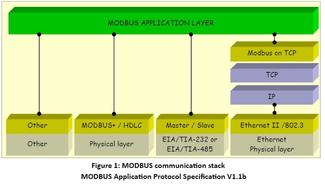
TCP mode is generally used on Ethernet networks, while MODBUS RTU and MODBUS ASCII modes are used on serial channels (rs232, rs485 etc.). These are the particularities of serial communications in MODBUS RTU and MODBUS ASCII modes:
| ASCII Mode |
RTU Mode |
|
| Characters |
ASCII ‘0’…’9’,’A’….’F’ |
Binary 0…255 |
| Error check |
LRC Longitudinal Redundancy Check |
CRC Cyclic Redundancy Check |
| Start of frame |
Character ‘:’ |
3.5 times t of character |
| End of frame |
Character CR/CL |
3.5 times t of character |
| Max. distance between chars. |
1 seg |
1.5 times t character |
| Data Bits |
1 |
1 |
| Data Bits |
7 |
8 |
| Parity |
Even/Odd/None |
Even/Odd/None |
| Stop Bits |
1 if there is parity 2 if none |
1 if there is parity 2 if none |

- Destination Address (1byte server number or Node Id): This is present in MODBUS ASCII, RTU, and TCP. For frames sent by the client, the server number field indicates the address of the server to which the frame is addressed. It allows up to 247 slaves to be addressed, with addresses from 1d to 247d (0x00 to 0xF7). The 0x00 is for Broadcast messages, so the first server starts with address 1 (from 1 to 247). In the case of frames sent by slaves, this byte serves to indicate to the client to whom the response belongs. That is, every time a server responds, it places its own address in the address byte, which allows the client to know which computer corresponds to each response. Broadcast frames have no associated response, and some implementations of MODBUS do not support broadcast frame.
- Frame ID (2bytes Transaction Identifier): This is present in MODBUS TCP and is used to associate questions sent by the client with answers sent by the server. It must be a unique number and can be used in different ways: it can be used as a simple "TCP sequence number" with a counter that increments on each request. It can also be used as an index or pointer to identify a transaction context, in order to memorize the current remote server and the pending MODBUS request.
Typically, in serial MODBUS deployments (ASCII and RTU), a client must submit a single request at a time and wait until they have received the response before sending the next one. This means that the customer must wait for the response to the first request before submitting a second request. In contrast, in MODBUS TCP implementations, this transaction ID allows multiple requests to be sent to the same server without having to wait for a confirmation to send the next request.
The number of requests accepted by a server depends on its capacity in terms of the number of resources and the size of the TCP windows. In the same way, the number of transactions initialized simultaneously by a client also depends on its resource capacity. This implementation parameter is called "NumberMaxOfClientTransaction" and should be described as one of the features of the MODBUS client. Depending on the type of device, this parameter can have a value from 1 to 16.
- Protocol ID (2 bytes): it is present in MODBUS TCP, and in the case of conventional MODBUS TCP it is 0.
- Length (2 bytes): it is present in MODBUS TCP and is used to indicate the total bytes that follow this field to the end of the message, i.e. the number of bytes after this field to the end of the ADU (the 2 bytes of the length are not counted in the value).
- Error check (LRC or CRC error handling): this is present in MODBUS ASCII and RTU. A different error detection system is used depending on the type of encoding used (ASCII or RTU). In the case of ASCII encoding it is the checksum (or Redundancy Check LRC Length) in module 16 expressed in ASCII (2 characters represent 1 byte), without considering the ":" or the "CR LF" of the frame. RTU encoding uses the CRC (Cyclical Redundancy Check) method encoded in 2 bytes (16 bits).
To calculate the CRC a 16-bit register is loaded all with '1's, OR is made with each of the 8-bit characters with the content of each byte and the result is shifted one bit to the left inserting a 0 in the position of least weight (the one on the right). The one on the left is extracted and examined: if it is 1 you do OR again with a preset value, if it is 0 you do not do any OR etc. and the process is repeated until the 8 shifts of the byte have been made. The following is a C implementation of the CRC calculation function (RTU mode):it tells the client who the answer belongs to. That is, every time a server responds, it places its own address in the address byte, which allows the client to know which computer corresponds to each response. Broadcast frames have no associated response, and some implementations of MODBUS do not support broadcast frame.
- Function code (1 byte Operation code): Indicates the type of operation we want to perform on the server. Operations can be classified into two types:
- Read/write in memory: to query or modify the state of the server memory map records.
- Server control orders: to perform some action on the server.
The opcode can take any value between 0 and 127 (the highest bit 0x80 is reserved for marking the answer as an exception). Each code corresponds to a certain operation. Some of these codes are considered standard and are accepted and interpreted equally by all devices claiming to be compatible with MODBUS, while other codes are each manufacturer's own implementations. In other words, some manufacturers make their own implementations of these "non-standard" codes. The most commonly used are 1,2,3,4,5,6,7,15 and 16.
The server also uses the operation code of the response frame to confirm whether the operation has been executed successfully or not. If it has gone well, the server responds with the same opcode that has been sent to it, while if any error has occurred, it also responds with the same opcode but with its heaviest bit at 1 (0x80) and a byte in the data field indicating the error/exception code that has taken place.
- Data (n bytes Address, data, and subfunctions): This field contains the information needed to perform the operation indicated by the opcode. Each operation will need one parameter or another, so the content and number of bytes in this field will vary depending on the operation. A frequent field in this block is the accessed MODBUS address.
The server's responses may or may not have a data field depending on the operation.
As indicated in the section dedicated to the Function code, in cases where an error occurs, the server will respond with an error/exception frame. When a command execution fails on the server, it responds with an error/exception frame by setting 1 to the heaviest bit of the function code (0x80). With this bit the client knows that the server has failed when trying to execute the sent command, but for more detail on the type of error, it has to check the data field that follows the Function code field:
| Code |
Number |
Meaning |
| 01 |
ILLEGAL FUNCTION |
The received function code does not correspond to any command available on the server. |
| 02 |
ILEGAL DATA ADRESS |
The address indicated in the frame does not correspond to any valid server address. |
| 03 |
ILLEGAL DATA VALUE |
The value sent to the server is invalid. |
| 04 |
SLAVE DEVICE FAILURE |
The server has received the frame and started processing it, but some error has occurred and it has not been able to finish the task. |
| 05 |
ACKNOWLEDGE |
The server has received the frame and is processing it, but this will take a bit of a long time. This response prevents the customer from considering a timeout error. The client can later send a frame of type Poll Program Complete to verify if it has completed the command. |
| 06 |
SLAVE DEVICE BUSY |
The server is busy performing another task and cannot attend to that request at that moment, so the client will have to retry later. |
- Discretes Input (Discrete Input bank or also Digital Input): 1 address -> 1 unique read-only bit. This type of data can be provided by an I/O system and read from within the application. Each bank address corresponds to 1 Boolean. Addresses in this range are usually accessed with function 2.
- Coils (Coil bank or also Digital Outputs): 1 -> 1 unique read-write bit. This type of data can be modified by an application program and published by an I/O device. Each bank address corresponds to 1 Boolean. Addresses in this range are usually accessed by functions 1 (read), 5 (write), 15 (multiple write).
- Input Registers (Analog Inputs bank): 1 -> 16-bit read-only word. This type of data can be provided by an I/O system and read from within the application. Each bank address corresponds to a value of 2 bytes. Addresses in this range are accessed using function 4 (read).
- Holding Registers (bank of Retention Registers or also Analog Outputs): 1 -> 16-bit read-write word. This type of data can be modified by an application program and published by an I/O device. Each bank address corresponds to a value of 2 bytes. They are accessed with functions 3 (read), 6 (write) or 16 (multiple write).
As indicated, in banks of the type Discretes Input and Coils each exposed address corresponds to a boolean (1bit). In banks dedicated to Input Registers or Holding Registers, each exposed address is 16 bits. Then, internally, both the server and client computers can organize and map that data into a single range of addresses. They can also regroup, split, and interpret the data as the type of data that suits you. Access to one or the other bank by the client depends on the MODBUS command used (each Function Code implies access to one bank or another on the MODBUS server).
It is obvious that all data handled through MODBUS (bits, registers) must be located in the memory of the device's application, but the internal physical address in the memory or in the application should not be confused with the bank's MODBUS address used to reference data in communications. It is up to the application to link the internal memory addresses to the addresses of the different MODBUS banks.
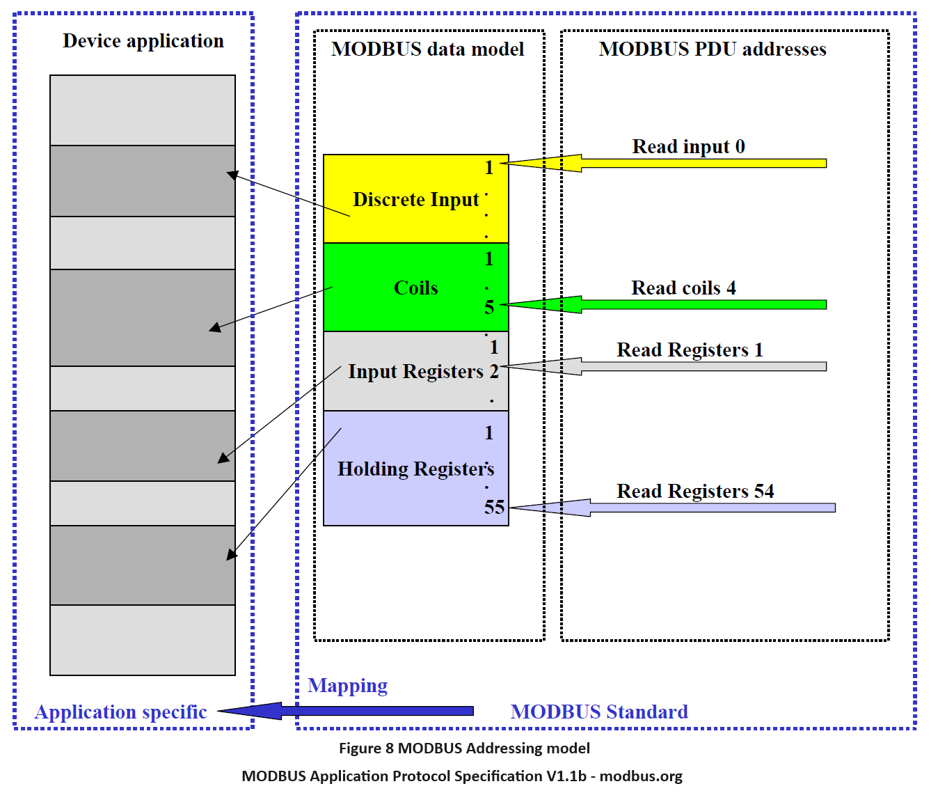
Therefore the pre-mapping between the MODBUS data address model and the device application is totally free and specific to the device vendor/manufacturer, although traditionally many devices mapped the previous 4 buckets to these internal application address ranges.ion:
@00001-10000 : for Coils bench data.
@10001-20000 : for bank data Discretes Input.
@20001-30000 : el protocolo MODBUS estándar no hace uso de este rango de direcciones.
@30001-40000 : for bank data Input Registers
@40001-50000 : for bank data Holding Registers.
The application-level data size/type associated with each MODBUS data can also be considered as such.
When setting the address of a variable or other element in the MODBUS address map, we address with 1 unit less than that of the register we want to access, so that if we wanted to access the relay @ 127d, we would do so by placing the value 126d in the byte of the address field. Other examples:
- Relay number 1 of a controller would be addressed with the value 0000 in the address field of a MODBUS message.
- A controller's 0x007F relay (127d) would be addressed with the value 0x007E (126d) in the address field of a MODBUS message.
- Holding Register 40001 would be accessed by placing the value 0000 in the message address field. As you can see, the function code for access to the Holding Registers implies access to the address '4XXXX'.
- Holding Register 40108 is accessed by reading from the address 0x006B (107d).
Some manufacturers express the address in a compound way, separating the word address and the bit address: e.g. word 0x30 bit 1
En C:
“…
#definePOLY0xA001
unsignedcrc16(char*buf,intlen)
{
char i;
unsigned crc;
crc^=*buf++;
for(i=0;i<8;i++){
if(crc&0x0001){
crc=(crc>>1)^POLY;
}else{
crc>>=1;
}
}
}
return(crc);
}
…”
“…
uint crc16(byte [ ] buf , uint len)
{
uint POLY=0xA001;
int crc;
uint i;
uint j;
j = 0;
for (crc = 0xFFFF; len != 0; len --){
crc ^= buf[j];
j++;
for (i = 0; i < 8; i ++){
if ((crc & 0x0001)>0){
crc = (crc >> 1) ^ POLY;
}else{
crc >>= 1;
}
}
}
return (crc);
}
…”
|
Field Name |
Example (HEX) |
2x8bits ASCII mode |
8bits RTU mode |
|
Header |
: |
None |
|
|
Server address |
06 |
“06” |
0000 0110 |
|
Function |
03 |
“03” |
0000 0011 |
|
Start address Hi |
00 |
“00” |
0000 0000 |
|
Start address Lo |
6B |
“6B” |
0110 1011 |
|
Registers Numb. Hi |
00 |
“00” |
0000 0000 |
|
Registers Numb. Lo |
03 |
“03” |
0000 0011 |
|
Error Check |
LRC (2 characters) |
CRC (16 bits) |
|
|
End of frame |
CR LF |
None |
|
|
Total: |
17 bytes |
8 bytes |
|
Field Name |
Example (HEX) |
2x8bits ASCII mode |
8bits RTU mode |
|
Header |
: |
None |
|
|
Server address |
06 |
“06” |
0000 0110 |
|
Function |
03 |
“03” |
0000 0011 |
|
Number of data bytes |
06 |
“06” |
0000 0110 |
|
Value 0 Hi |
02 |
“02” |
0000 0010 |
|
Value 0 Lo |
2B |
“2B” |
0010 1011 |
|
Value 1 Hi |
00 |
“00” |
0000 0000 |
|
Value 1 Lo |
00 |
“00” |
0000 0000 |
|
Value 2 Hi |
00 |
“00” |
0000 0000 |
|
Value 2 Lo |
63 |
“63” |
0110 0011 |
|
Error Check |
LRC (2 characters) |
CRC (16 bits) |
|
|
End of frame |
CR LF |
none |
|
|
Total: |
23 bytes |
11 bytes |
- Function 1 Read Coil Status
- Function 2 Read Input Status
- Function 3 Read Holding Registers
- Function 4 Read Input Registers
- Function 5 Force Single Coil
- Function 6 Preset Single Register
- Function 7 Read Exception Status
- Function 8 Diagnostics
- Function 9 Program 484
- Function 10 Poll 484
- Function 11 Fetch Communication Event Counter
- Function 12 Fetch Communication Event Log
- Function 13 Program Controller
- Function 14 Poll Controller
- Function 15 Force Multiple Coils
- Function 16 Preset Multiple Registers
- Function 17 Report Slave ID
- Function 18 Program 884/M84
- Function 19 Reset Comm. Link
- Function 20 Read General Reference
- Function 21 Write General Reference
- Function 22 Mask Write 4X Register
- Function 23 Read/Write 4X Registers
- Function 24 Read FIFO Queue
Allows the reading of the status of the DIs (Discrete Input Bank or also Digital Input) or DOs (DO Bitbank) of the server. To do this, the client requests the number of bits it wants to read from a given address. Each address points to a 1-bit register with the state of the digital input or output. The server responds by indicating the number of consecutive bits it returns and their values. All bits of the byte are used in the response frame, and there can be up to 256 bytes.
MODBUS RTU:
Client query:
ADU: Server No.
PDU: Operation Code: 0x01 o 0x02
PDU: Address register (de 1 bit) a leer H
PDU: Address register (de 1 bit) a leer L
PDU: Num of bits to read Hi
PDU: Num of bits to read Lo
ADU: CRC(16): H
ADU: CRC(16):
Server reply:
ADU: Server No.
PDU: Operation Code: 0x01 o 0x02
PDU: Num of read bytes: 1 byte
PDU: Bytes: max 256 bytes
ADU: CRC(16): H
ADU: CRC(16): L
MODBUS TCP:
Client query:
ADU: Transaction ID H
ADU: Transaction ID L
ADU: Protocol ID H
ADU: Protocol ID L
ADU: Length (in bytes) H
ADU: Length (in bytes) L
ADU: Server No.
PDU: Operation Code: 0x01 o 0x02
PDU: Address of the register (de 1 bit) to read Hi
PDU: Address of the register (de 1 bit) to read Lo
PDU: Num of bits to read H
PDU: Num of bits to read L
Server reply:
ADU: Transaction ID H
ADU: Transaction ID L
ADU: Protocol ID H
ADU: Protocol ID L
ADU: Length (in bytes) H
ADU: Length (in bytes) L
ADU: Server No.
PDU: Operation Code: 0x01 o 0x02
PDU: Num of read bytes 1 byte
PDU: Bytes: de 1 a 256 bytes
Ej 1 MODBUS TCP:
Q:[00][04][00][00][00][06][01][01][00][00][00][08]
ADU: Transaction ID: 4 : [00][04]
ADU: Protocol ID: 0 : [00][00]
ADU: Length: 6 : [00][06]
ADU: Server No.: 1 : [01]
PDU:.000 0001 = Function Code: Read Coils (1): [01]
PDU: Address register: 0 : [00][00]
PDU: Num of bits to read: 8: [00][08]
R:[00][04][00][00][00][04][01][01][01][00]
ADU: Transaction ID: 4 : [00][04]
ADU: Protocol ID: 0 : [00][00]
ADU: Length: 4 : [00][04]
ADU: Server No.: 1
PDU: .000 0001 = Function Code: Read Coils (1)
PDU: Byte Count: 1
PDU: Bit 0 : 0
Bit 1 : 0
Bit 2 : 0
Bit 3 : 0
Bit 4 : 0
Bit 5 : 0
Bit 6 : 0
Bit 7 : 0
Ej 2 MODBUS TCP:
Q:[00][02][00][00][00][06][01][02][00][01][00][01]
ADU: Transaction ID: 2 : [00][02]
ADU: Protocol ID: 0 : [00][00]
ADU: Length: 6 : [00][06]
ADU: Server No.: 1 : [01]
PDU: .000 0010 = Function Code: Read Discrete Inputs (2)
PDU: Address register: 1 : [00][01]
PDU: Num of bits to read: 1: [00][01]
R:[00][02][00][00][00][04][01][02][01][00]
ADU: Transaction ID: 2 : [00][02]
ADU: Protocol ID: 0 : [00][00]
ADU: Length: 4 : [00][04]
ADU: Server No.: 1
PDU: .000 0010 = Function Code: Read Discrete Inputs (2)
PDU: Byte Count: 1
PDU: Bit 0 : 0
Bit 1 : 0
Bit 2 : 0
Bit 3 : 0
Bit 4 : 0
Bit 5 : 0
Bit 6 : 0
Bit 7 : 0
Allows the reading of the value of the AIs (bank of Input Registers or also Analog Inputs) or AOs (bank of Output Registers or also Analog Outputs) of the server. The client indicates the base address and number of words to read from this address, while the server indicates in the response the number of bytes returned, followed by these requested values. Although you are actually writing in the range of registers or numerical values, the registers are addressed from the address 0. Each word or data written using this function corresponds to 2 bytes (1 word = 16 bits).
MODBUS RTU:
Client query:
ADU: Server No.
PDU: Operation Code: 0x03 o 0x04
PDU: Address of the register to read Hi
PDU: Address of the register to read Lo
PDU: Num of values to read: max 128 values (2 bytes per value)
ADU: CRC(16): H
ADU: CRC(16): L
Server reply:
ADU: Server No.
PDU: Operation Code: 0x03 o 0x04
PDU: Num of read bytes: 1 byte
PDU: Received values: max 128 values (2 bytes per value)
ADU: CRC(16): Hi
ADU: CRC(16): Lo
Ej 1 MODBUS RTU:
Q:[01][03][01][00][00][06][C4][34]
R:[01][03][0C][20][81][00][00][00][00][00][00][00][00][1C][01][76][F1]
Ej 2 MODBUS RTU:
Q:[0A][04][00][00][00][0A][71][76]
ADU: Server No. / peripheral 10 : [0A]
PDU: Operation Code:.000 0100 = Function Code: Read Input Registers 4 : [04]
PDU: Address of the register to start reading from: 0 : [00][00]
PDU: Num of values to read: number of registers to read: 10 : [00][0A]
ADU: CRC [71][76]
R:[0A][04][14][00][00][08][4D][00][00][23][28][00][00][0F][A0][00][00][00][90][00][00][00][60][CB][2E]
ADU: Server No. / peripheral who replies: 10 : [0A]
PDU: Operation Code:.000 0100 = Function Code: Read Input Registers 4 : [4]
PDU: NºReceived values: Num of received bytes: 20 : [14].
PDU: Received values:
00 00 08 4D : V1x 10 (register 00 Hex) with decimal value 212,5 V
00 00 23 28 : mA 1, in decimal 9000 mA
00 00 0F A0 : W 1, in decimal 4000 W
00 00 00 90 : varL 1, in decimal 144 varL
00 00 00 60 : PF1 x 100, in decimal 96
ADU: CRC(16): [CB][2E]
Ej 3 MODBUS RTU:
Q:[01][03][00][30][00][10][44][09]
ADU: Server No. / peripheral 1 : [01]
PDU: Operation Code:.000 0011 = Function Code: Read Holding Registers 3 : [03]
PDU: Address register a leer. Record where the reading is to begin 48 : [00][30]
PDU: No. of data to be read: number of records to be read: 16 : [00][10]
ADU: CRC [44][09]
R:[01][03][20][00][00][00][00][00][00][00][00][00][00][00][00][00][00][00][00][00][00][00][00][00][00][27][0F][16][18][00][00][2E][DF][00][00][42][CF]
ADU: Server No. / peripheral 1 : [01]
PDU: Operation Code:.000 0011 = Function Code: Read Holding Registers 3 : [03]
PDU: No. of data received: Number of bytes received 32 : [20].
PDU: Data Received: (32 bytes to 2 bytes per record: 16 records
00 00 00 00 00 00 00 00 00 00 00 00 00 00 00 00 00 00 00 00 00 00 27 0F 16 18 00 00 2E DF 00 00
ADU: CRC(16): [42][CF]
MODBUS TCP:
Client query:
ADU: Transaction ID H
ADU: Transaction ID L
ADU: Protocol ID H
ADU: Protocol ID L
ADU: Length (in bytes) H
ADU: Length (in bytes) L
ADU: Server No.
PDU: Operation Code: 0x03 o 0x04
PDU: No. of data to be read max 128 (2 bytes per data) to read H
PDU: No. of data to be read max 128 (2 bytes per data) to read L
Server reply:
ADU: Transaction ID H
ADU: Transaction ID L
ADU: Protocol ID H
ADU: Protocol ID L
ADU: Length (in bytes) H
ADU: Length (in bytes) L
ADU: Server No.
PDU: Operation Code: 0x03 o 0x04
PDU: No. of Bytes Read: 1 byte
PDU: Data: Max 128 data (2 bytes per data = 256 bytes)
Ej 1 MODBUS TCP:
Q:[00][04][00][00][00][06][01][04][00][20][00][01]
ADU: Transaction ID: 4 : [00][04]
ADU: Protocol ID: 0 : [00][00]
ADU: Length: 6 : [00][06]
ADU: Server No.: 1 : [01]
PDU: .000 0100 = Function Code: Read Input Registers (4)
PDU: Address register: 32 : [00][20]
PDU: Data to Read (words): 1: [00][01]
R:[00][04][00][00][00][05][01][04][02][00][00]
ADU: Transaction ID: 4 : [00][04]
ADU: Protocol ID: 0 : [00][00]
ADU: Length: 5 : [00][05]
ADU: Server No.: 1
PDU: .000 0100 = Function Code: Read Input Registers (4) : [04]
PDU: Byte Count: 2 : [02]
PDU: Data (Words): [00][00]
Function 5 (Force Single Coil):
Allows you to modify the state of a server DO. That is, through this command we can modify bits of any of the internal variables of the server or order the execution or activation of a controller. It acts on the bank of Coils or Digital Outputs (they can be controls, relays, digital outputs or simple bits in memory). The client specifies the address of the bit or command it wants to modify followed by 0x00 to set it to 0 or 0xFF to set it to 1. The server responds with a similar frame indicating the address it has modified and the value it has set in the bit or command. Each piece of data written using this function corresponds to 1 bit.
MODBUS RTU:
Client query:
ADU: Server No.
PDU: Operation Code: .000 0101 = Function Code: Write Single Coil (5) : [05]
PDU: Address of the Written Bit H
PDU: Address of the Written Bit L
PDU: Desired state for the bit: 0xXX (0x00 : 0 , 0xFF : 1) + ¿0x00 padding?
ADU: CRC(16): H
ADU: CRC(16): L
Server reply:
ADU: Server No.
PDU: Operation Code: .000 0101 = Function Code: Write Single Coil (5) : [05]
PDU: Address of written bit H
PDU: Address of written bit L
PDU: State of the written bit: 0xXX (0x00 : 0 , 0xFF : 1) + ¿0x00 padding?
ADU: CRC(16): H
ADU: CRC(16): L
Ej 1 MODBUS RTU:
Q:[01][05][00][01][FF][00][DD][FA]
ADU: Server No. 1 : [01]
PDU: Operation Code 5: [05]
PDU: Address of the bit to write 1 : [00][01]
PDU: Desired state for the bit: 1 : [FF] (0x00 : 0 , 0xFF : 1) + ¿[00] padding?
ADU: CRC(16): [DD][FA]
R:[01][05][00][00][FF][00][8C][3A]
ADU: Server No. 1 : [01]
PDU: Operation Code: .000 0101 = Function Code: Write Single Coil (5) : [05]
PDU: Address of written bit 1 : [00][01]
PDU: State of the written bit 1 : [FF] (0x00 : 0 , 0xFF : 1) + ¿[00] padding?
ADU: CRC(16): [8C][3A]
Ej 2 MODBUS RTU:
Q:[01][05][00][00][00][00][CD][CA]
ADU: Server No. 1 : [01]
PDU: Operation Code: .000 0101 = Function Code: Write Single Coil (5) : [05]
PDU: Address of the bit to write 0 : [00][00]
PDU: Desired state for the bit 0 : [00] (0x00 : 0 , 0xFF : 1) + ¿[00] padding?
ADU: CRC(16): [CD][CA]
R:[01][05][00][01][00][00][CD][CA]
ADU: Server No. 1 : [01]
PDU: Operation Code: .000 0101 = Function Code: Write Single Coil (5) : [05]
PDU: Address of written bit 0 : [00][00]
PDU: State of the written bit: [00] (0x00 : 0 , 0xFF : 1) + ¿ [00] padding?
ADU: CRC(16):[CD][CA]
MODBUS TCP:
Client query:
ADU: Transaction ID H
ADU: Transaction ID L
ADU: Protocol ID H
ADU: Protocol ID L
ADU: Length (in bytes) H
ADU: Length (in bytes) L
ADU: Server No.
PDU: Operation Code: .000 0101 = Function Code: Write Single Coil (5) : [05]
PDU: Address of the bit to write H
PDU: Address of the bit to write L
PDU: Desired state for the bit: 0xXX (0x00 : 0 , 0xFF : 1) + ¿0x00 padding?
Server reply:
ADU: Transaction ID H
ADU: Transaction ID L
ADU: Protocol ID H
ADU: Protocol ID L
ADU: Length (in bytes) H
ADU: Length (in bytes) L
ADU: Server No.
PDU: Operation Code: .000 0101 = Function Code: Write Single Coil (5) : [05]
PDU: Address of written bit H
PDU: Address of written bit L
PDU: State of the written bit: 0xXX (0x00 : 0 , 0xFF : 1) + ¿0x00 padding?
Ej 1 MODBUS TCP:
Q:[00][03][00][00][00][06][01][05][00][00][00][00]
ADU: Transaction ID 3 : [00][03]
ADU: Protocol ID 0 : [00][00]
ADU: Length (in bytes) 6 : [00][06]
ADU: Server No. 1 : [01]
PDU: Operation Code: .000 0101 = Function Code: Write Single Coil (5) : [05]
PDU: Address of the bit to write [00][00]
PDU: Desired state for the bit: 0 ([00] : 0 , [FF] : 1) + ¿ [00] Padding ?
R:[00][03][00][00][00][06][01][05][00][00][00][00]
ADU: Transaction ID 3 : [00][03]
ADU: Protocol ID 0 : [00][00]
ADU: Length (in bytes) 6 : [00][06]
ADU: Server No. 1 : [01]
PDU: Operation Code: .000 0101 = Function Code: Write Single Coil (5) : [05]
PDU: Address of written bit 0 : [00][00]
PDU: State of the written bit 0 : [00] ([00] : 0 , [FF] : 1) + ¿ [00] Padding ?
Function 6 (Preset Single Register) :
Allows writing to the server's AOs (either a signal or internal value of the computer), and therefore acts on the bank of Retention Registers or also Analog Outputs. We must indicate the direction of the value we want to modify and the magnitude we want to assign to it. Then the server should respond with the address of the data it has modified and the value it has assigned to it, which should match the one sent. Each piece of data written using this function corresponds to 2 bytes (1 word = 16 bits).
MODBUS RTU:
Client query:
ADU: Server No.
PDU: Operation Code: .000 0110 = Function Code: Write Single Register (6) : [06]
PDU: Address of the data to be written H
PDU: Address of the data to be written L
PDU: Value of the data to be written H
PDU: Value of the data to be written L
ADU: CRC(16): H
ADU: CRC(16): L
Server reply:
ADU: Server No.
PDU: Operation Code: .000 0110 = Function Code: Write Single Register (6) : [06]
PDU: Address of Written Data H
PDU: Address of Written Data L
PDU: Value of the register after writing H
PDU: Value of the register after writing L
ADU: CRC(16): H
ADU: CRC(16): L
Ej 1 MODBUS RTU:
Q:[01][06][01][F1][00][02][58][04]
ADU: Server No. 1 : [01]
PDU: Operation Code: .000 0110 = Function Code: Write Single Register (6) : [06]
PDU: Address of the data to be written 497 : [01][F1]
PDU: Value of the data to be written 2: [00][02]
ADU: CRC(16): [58][04]
R:[01][06][01][F1][00][02][58][04]
ADU: Server No. 1 : [01]
PDU: Operation Code: .000 0110 = Function Code: Write Single Register (6) : [06]
PDU: Address of Written Data 497 : [01][F1]
PDU: Value of the Register after Writing: [00][02]
ADU: CRC(16): [58][04]
MODBUS TCP:
Client request:
ADU: Transaction ID H
ADU: Transaction ID L
ADU: Protocol ID H
ADU: Protocol ID L
ADU: Length (in bytes) H
ADU: Length (in bytes) L
ADU: Server No.
PDU: Operation Code: .000 0110 = Function Code: Write Single Register (6) : [06]
PDU: Address of the data to be written H
PDU: Address of the data to be written L
PDU: Value of the data to be written H
PDU: Value of the data to be written L
Server reply:
ADU: Transaction ID H
ADU: Transaction ID L
ADU: Protocol ID H
ADU: Protocol ID L
ADU: Length (in bytes) H
ADU: Length (in bytes) L
ADU: Server No.
PDU: Operation Code: .000 0110 = Function Code: Write Single Register (6) : [06]
PDU: Address of Written Data H
PDU: Address of Written Data L
PDU: Valor del registro tras la escritura H
PDU: Valor del registro tras la escritura L
Ej 1 MODBUS TCP:
Q:[00][03][00][00][00][06][01][06][00][20][00][02]
ADU: Transaction ID 3 : [00][03]
ADU: Protocol ID 0 : [00][00]
ADU: Length (in bytes) 6 : [00][06]
ADU: Server No. 1 : [01]
PDU: Operation Code: .000 0110 = Function Code: Write Single Register (6) : [06]
PDU: Address of the data to be written 32 : [00][20]
PDU: Value of the data to be written: [00][02]
R:[00][03][00][00][00][06][01][06][00][20][00][02]
ADU: Transaction ID 3 : [00][03]
ADU: Protocol ID 0 : [00][00]
ADU: Length (in bytes) 6 : [00][06]
ADU: Server No. 1 : [01]
PDU: Operation Code: .000 0110 = Function Code: Write Single Register (6) : [06]
PDU: Address of Written Data 32 : [00][20]
PDU: Value of the register after Write 2: [00][20]
Function 7 (Read Exception Status) :
Allows the fast reading of a fixed byte from a server, which is usually the exception byte and reports the status of the computer. It has no byte address because the exception byte (internal to the server) is always read:
MODBUS RTU:
Client query:
ADU: Server No.
PDU: Operation Code: .000 0111 = Function Code: Read Exception Status (7)
ADU: CRC(16): H
ADU: CRC(16): L
Client query:
ADU: Server No.
PDU: Operation Code: .000 0111 = Function Code: Read Exception Status (7)
PDU: Exception byte value
ADU: CRC(16): H
ADU: CRC(16): L
Function 15 (Force Multiple Coils):
Allows the modsimultaneous creation of several bits of DOs on the server, passing them to OFF ('0') or ON ('1') as appropriate. It acts on the memory bank of the DOs. Thus, the initial address (address of the first bit or command to be modified) and the number and state of each of the successive controls (bits) to be modified are passed in the command.
MODBUS RTU:
Client query:
ADU: Server No.
PDU: Operation Code: .000 1111 = Function Code: Force Multiple Coils (15)
PDU: Base address of the of coils/controls (bits) H
PDU: Base address of the of coils/controls (bits) L
PDU: Number of coils/controls (bits) H
PDU: Number of coils/controls (bits) L
PDU: Number of bytes sent with the state of the controls (bits) H
PDU: Number of bytes sent with the state of the controls (bits) L
PDU: State of the first 8 controls (bits) to be modified
PDU: State of the next 8 controls (bits) to be modified,
...
PDU: State of the last 8 knobs (bits) to be modified
ADU: CRC(16): H L
Although the state of the DOs is specified bit by bit, the frames are composed of bytes, and this forces the states to be sent in groups of 8. The server should not pay attention to the excess bits, that is, it should not consider those that are above the last bit indicated in the field "number of controls to modify". Thus, if we wanted to modify 12 controls or relays from address 7, we would indicate address 7 as the source address, 12 as the number of controls to be modified, and in the control status field: 0x3C , 0x0B (the server will not consider those above 12th bit)
Relé: 14 13 12 11 10 09 08 07 - 22 21 20 19 18 17 16 15
Bits: 0 1 1 1 1 0 0 0 X X X X 1 0 1 1 Server reply:
ADU: Server No.
PDU No.: Operation Code: .000 1111 = Function Code: Force Multiple Coils (15) PDU: Force Multiple Coils (15)
PDU: Remote Base Address (bits) H
PDU: Remote Base Address (bits) L
PDU: Number of Forced Coils (bits) H
PDU: Number of forced controls (bits) L
ADU: CRC(16): H L
Function 16 (Preset multiple registers):
Allows writing to a group of consecutive registers in the AOS bank. You must specify the address from which you want to start updating values, the number of values you want to update, and the list of values you want to assign to these records.
MODBUS RTU:
ADU: Server No.
PDU: Operation Code: 0x10
PDU: Data base address: 2 bytes
PDU: Data number H
PDU: Data number L
PDU: Data value 0: 2 bytes
PDU: Data value 1: 2 bytes
...
PDU: Data value n-1: 2 bytes
ADU: CRC(16): H
ADU: CRC(16): L
Server reply:
ADU: Server No.
PDU: Operation Code: 0x10
PDU: Data base address: 2 bytes
PDU: Data number H
PDU: Data number L
ADU: CRC(16): H
ADU: CRC(16): L
Function 20 (Read General Reference):
Returns the contents of the Extended Memory (@6XXXX) registers. The server address, function code, the number of bytes to be read, and the error-checking bytes are sent in the frame. The data establishes the group or groups or references to be read. Each group is defined in a "sub-request" field that contains:
- Reference type: 1 byte (debe ser 6)
- Extended Memory file number: 2 bytes (0x01 a 0x0A)
- The address of the "file" from which we want to start reading: 2 bytes
- The number of records to be read: 2 bytes
The data to be read followed by the other fields must not exceed the maximum length allowed in MODBUS messages, i.e. 256 bytes.
MODBUS RTU:
Client query:
ADU: Server No.
PDU: Operation Code: .001 0100 = Function Code: Read General Reference (20) : [14]
PDU: Byte Count 0x0E
PDU: Data: Sub–Req 1, Reference Type 0x06
PDU: Data: Sub–Req 1, File Number Hi 0x00
PDU: Data: Sub–Req 1, File Number Lo 0x04
PDU: Data: Sub–Req 1, Starting Addr Hi 0x00
PDU: Data: Sub–Req 1, Starting Addr Lo 0x01
PDU: Data: Sub–Req 1, Register Count Hi 0x00
PDU: Data: Sub–Req 1, Register Count Lo 0x02
PDU: Data: Sub–Req 2, Reference Type 0x06
PDU: Data: Sub–Req 2, File Number Hi 0x00
PDU: Data: Sub–Req 2, File Number Lo 0x03
PDU: Data: Sub–Req 2, Starting Addr Hi 0x00
PDU: Data: Sub–Req 2, Starting Addr Lo 0x09
PDU: Data: Sub–Req 2, Register Count Hi 0x00
PDU: Data: Sub–Req 2, Register Count Lo 0x02
ADU: CRC(16)
Server reply:
ADU: Server No.
PDU: Operation Code: .001 0100 = Function Code: Read General Reference (20) : [14]
PDU: Byte Count 0x0C
PDU: Data: Sub–Res 1, Byte Count 0x05
PDU: Data: Sub–Res 1, Reference Type 0x06
PDU: Data: Sub–Res 1, Register Data Hi 0x0D
PDU: Data: Sub–Res 1, Register Data Lo 0xFE
PDU: Data: Sub–Res 1, Register Data Hi 0x00
PDU: Data: Sub–Res 1, Register Data Lo 0x20
PDU: Data: Sub–Res 2, Byte Count 0x05
PDU: Data: Sub–Res 2, Reference Type 0x06
PDU: Data: Sub–Res 2, Register Data Hi 0x33
PDU: Data: Sub–Res 2, Register Data Lo 0xCD
PDU: Data: Sub–Res 2, Register Data Hi 0x00
PDU: Data: Sub–Res 2, Register Data Lo 0x40
ADU: CRC(16)
Function 21 (Write General Reference):
Modifies the content of the registers in the Extended Memory. This function allows you to work on groups of registers that do not have to be contiguous (internally they must be contiguous). Each group is defined in a "sub-request" field that contains:
- Reference type: 1 byte (must be 6)
- Extended Memory file number: 2 bytes (0x01 a 0x0A)
- The address of the "file" from which we want to start reading: 2 bytes
- The number of records to be read: 2 bytes
Los datos a leer seguidos de los demas campos no debe superar la Length máxima permitida en los mensajes MODBUS, es decir los 256 bytes.
MODBUS RTU:
Client query:
ADU: Server No.
PDU: Operation Code: .001 0101 = Function Code: Write General Reference (21) : [15]
PDU: Byte Count 0x0D
PDU: Data: Sub–Req 1, Reference Type 0x06
PDU: Data: Sub–Req 1, File Number Hi 0x00
PDU: Data: Sub–Req 1, File Number Lo 0x04
PDU: Data: Sub–Req 1, Starting Addr Hi 0x00
PDU: Data: Sub–Req 1, Starting Addr Lo 0x07
PDU: Data: Sub–Req 1, Register Count Hi 0x00
PDU: Data: Sub–Req 1, Register Count Lo 0x03
PDU: Data: Sub–Req 1, Register Data Hi 0x06
PDU: Data: Sub–Req 1, Register Data Lo 0xAF
PDU: Data: Sub–Req 1, Register Data Hi 0x04
PDU: Data: Sub–Req 1, Register Data Lo 0xBE
PDU: Data: Sub–Req 1, Register Data Hi 0x10
PDU: Data: Sub–Req 1, Register Data Lo 0x0D
ADU: CRC(16)
Server reply:
ADU: Server No.
PDU: Operation Code: .001 0101 = Function Code: Write General Reference (21) : [15]
PDU: Byte Count 0x0D
PDU: Data:Sub–Req 1, Reference Type 0x06
PDU: Data:Sub–Req 1, File Number Hi 0x00
PDU: Data:Sub–Req 1, File Number Lo 0x04
PDU: Data:Sub–Req 1, Starting Addr Hi 0x00
PDU: Data:Sub–Req 1, Starting Addr Lo 0x07
PDU: Data:Sub–Req 1, Register Count Hi 0x00
PDU: Data:Sub–Req 1, Register Count Lo 0x03
PDU: Data:Sub–Req 1, Register Data Hi 0x06
PDU: Data:Sub–Req 1, Register Data Lo 0xAF
PDU: Data:Sub–Req 1, Register Data Hi 0x04
PDU: Data:Sub–Req 1, Register Data Lo 0xBE
PDU: Data:Sub–Req 1, Register Data Hi 0x10
PDU: Data:Sub–Req 1, Register Data Lo 0x0D
ADU: CRC(16)