- how I electrified and added MIDI connectivity to a spanish guitar -


Modifying the guitar and installing the pickup system
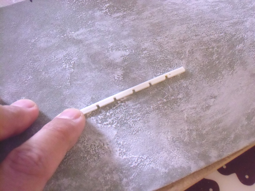
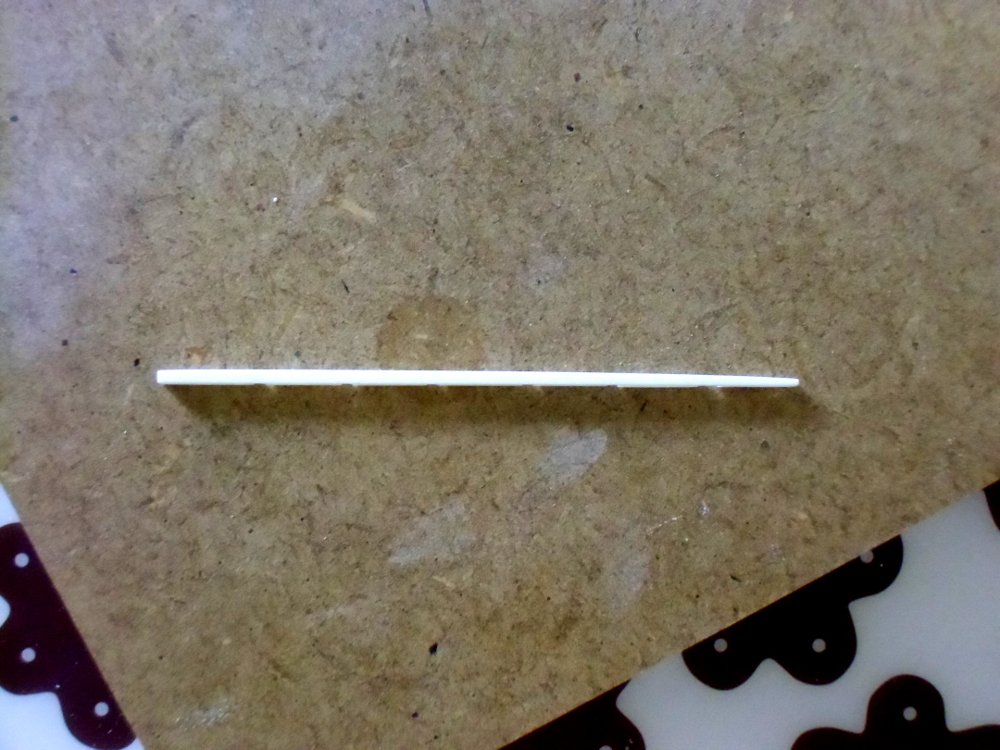
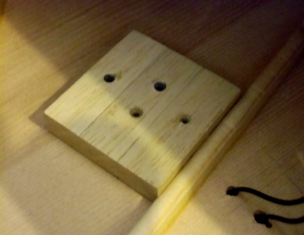
Once I had received the pickup system and bought the guitar, I started to work. First step was modifying the guitar bridge to place the piezo pickup on it. I removed the guitar strings, made wider the saddle slot, drilled six holes inside the saddle slot to pass the wires of each piezo sensor, and built a thin support for them. The function of this thin support is setting the right height of each piezo sensor to keep the right distance between each string and the fingerboard. Building it was one of the most delicate parts of the project.
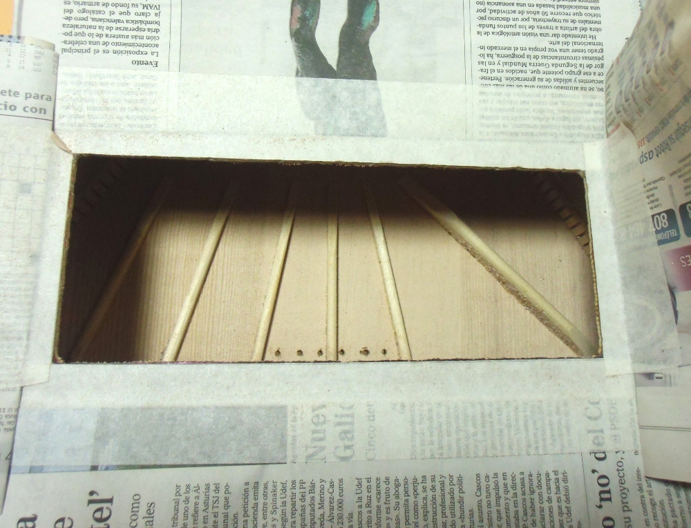
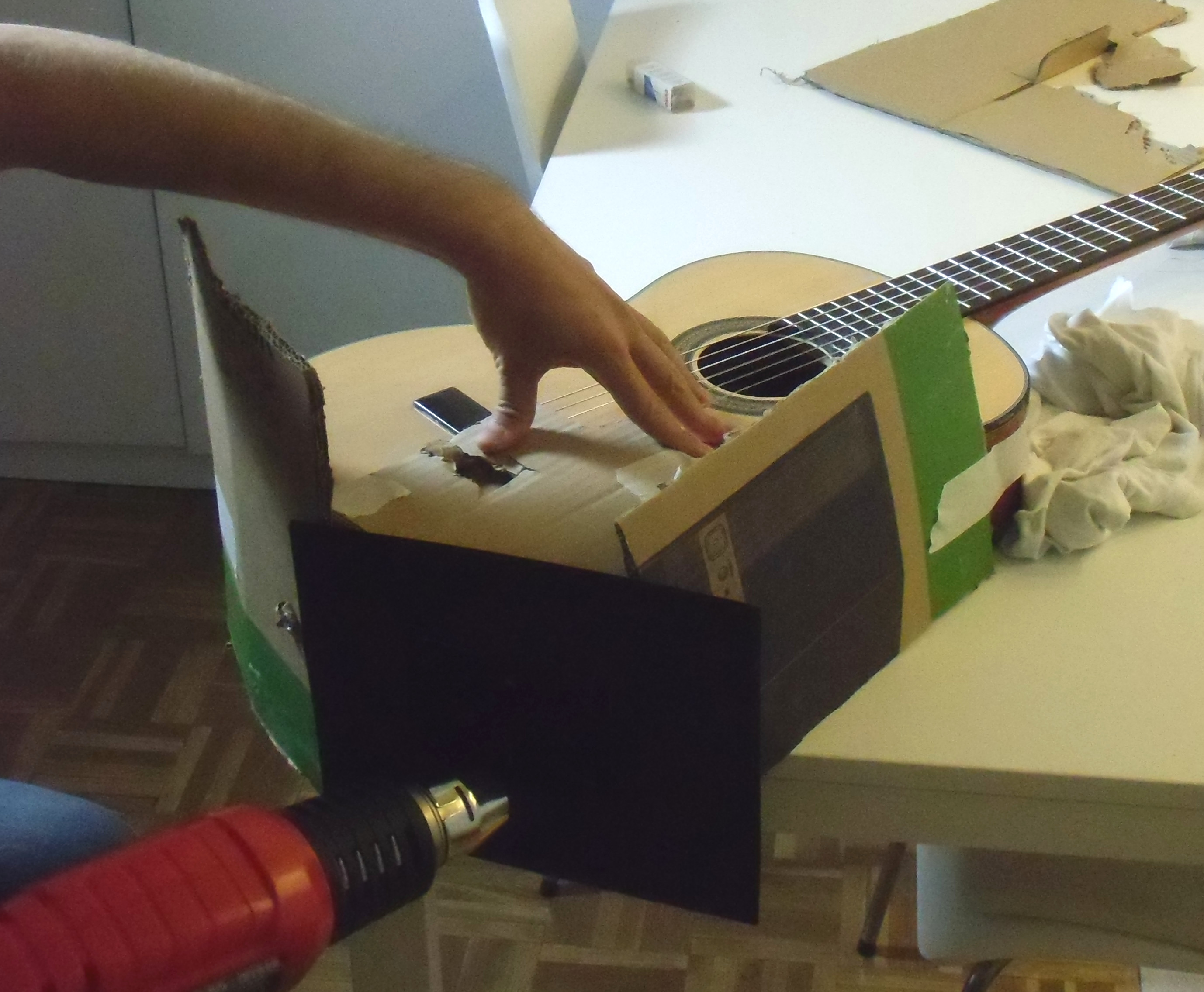
Before starting the modifications on the guitar I covered the working area with paper and masking tape to avoid damaging or scratching it. I also placed some old clothes over the table to rest the guitar over them instead of over the table raw surface.
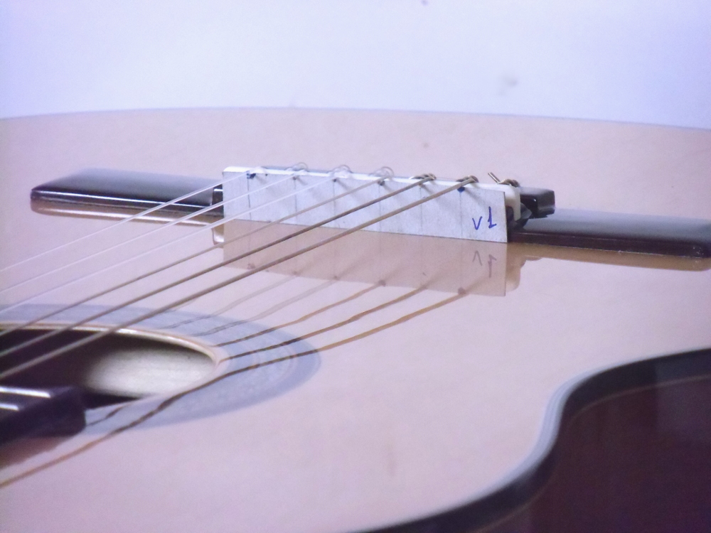
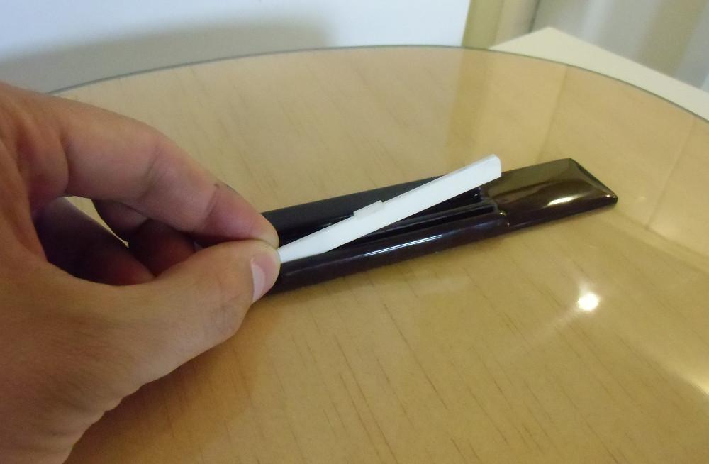

a template to measure the original height of the strings. Removed the original saddle and made the slot wider
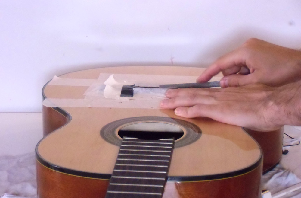
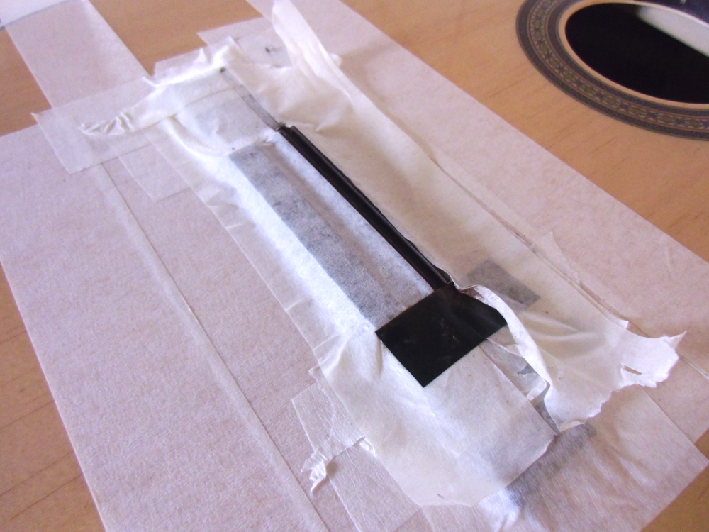

made the saddle slot wider, and drilled the holes to pass the independent piezo pickup wires

adjusting the pickup support, and the pickups nearly installed on the guitar
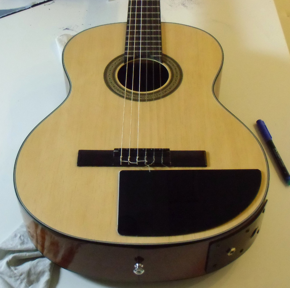
Next step, after having installed the piezo sensors, was adding a black "polycril" beautifying plate in the front side of the guitar box, and making some holes on it to insert the volume and tone potentiometers and the MIDI control push buttons.
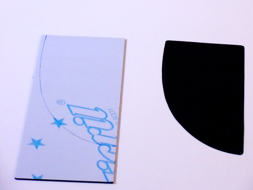
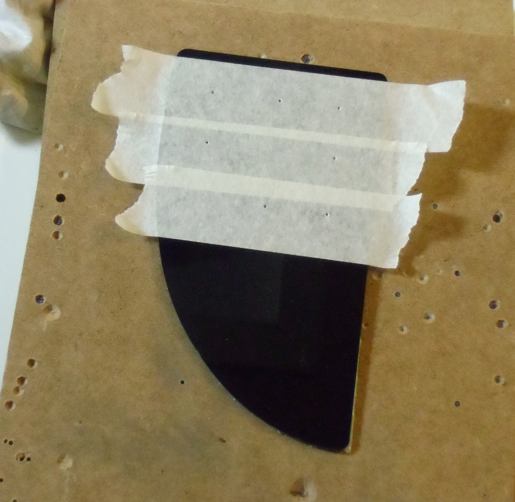
cutting the black "polycril" beautifying plate for the volume, tone and MIDI controls
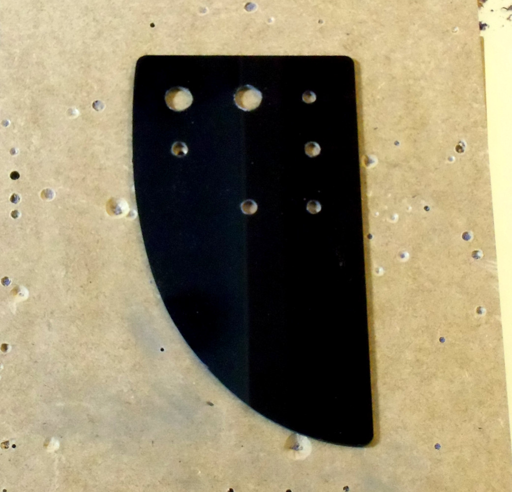
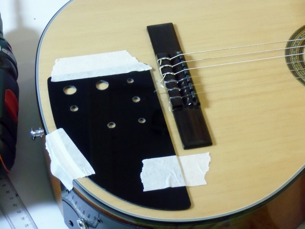
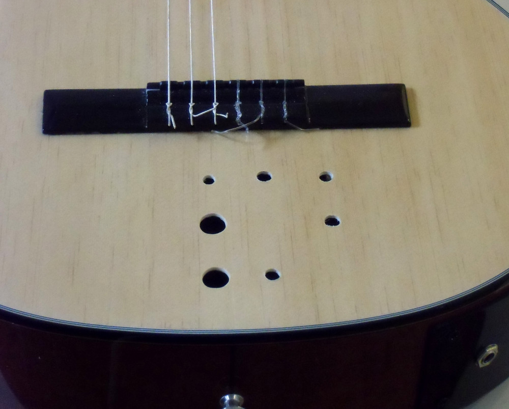
making the holes for the controls
When I bought the kit I didn't know that it used concentric potentiometers and didn't order the special knobs for them. But when I received it I realized that I wouldn't be able to use normal knobs with it. Instead of ordering new knobs for that special concentric potentiometers I decided to adapt some standard knobs by myself.
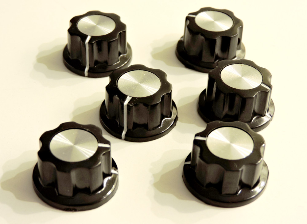
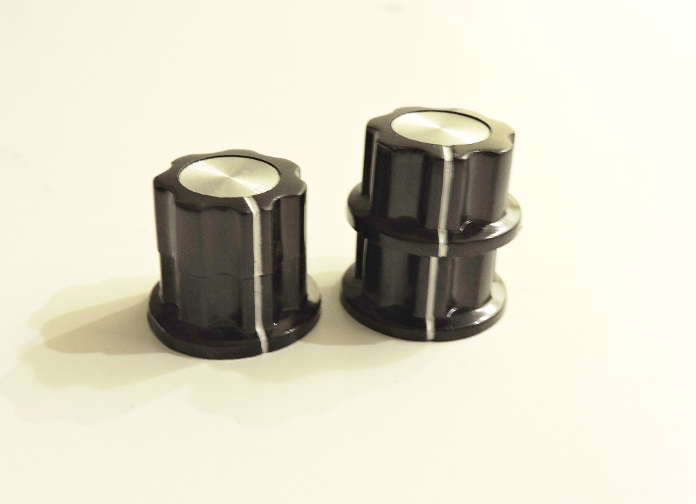
the knobs for the concentric potentiometers were done using 2 standard knobs
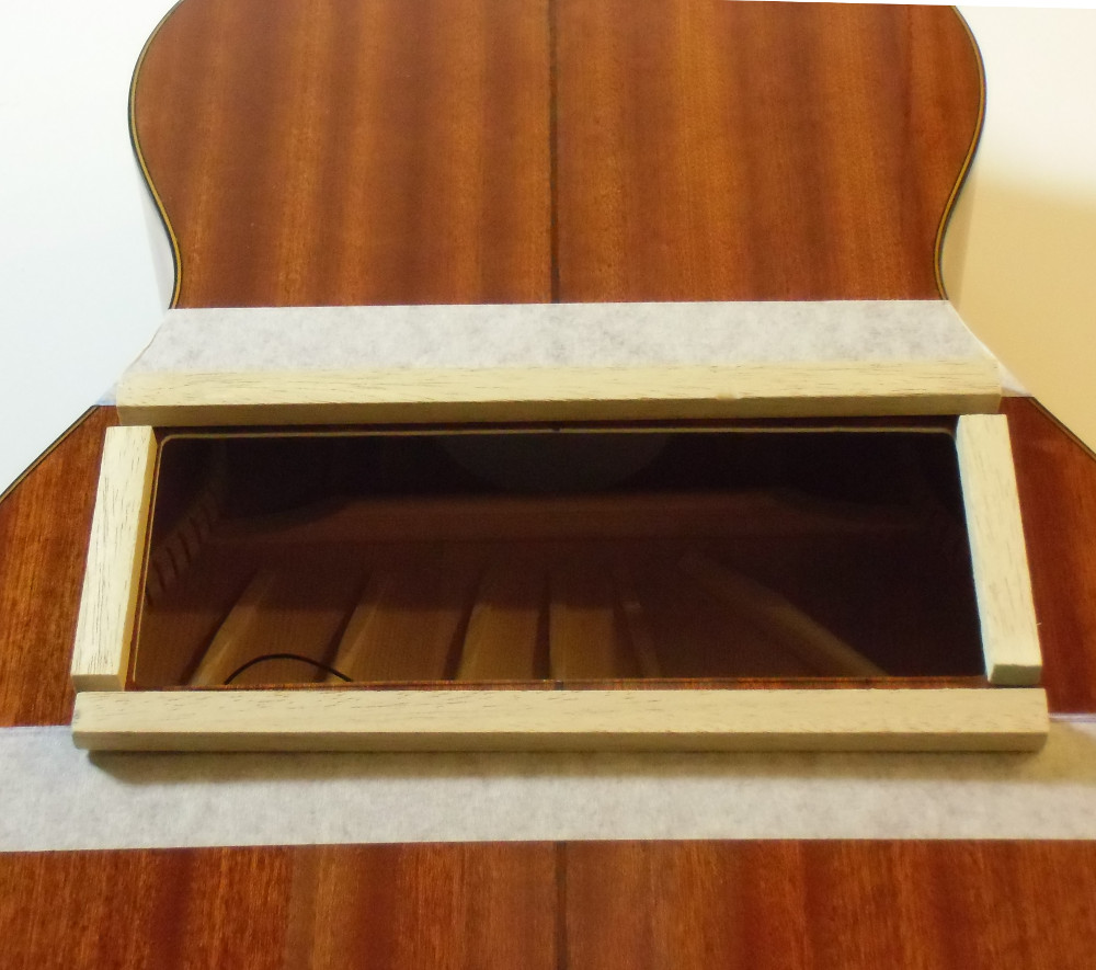
I had to make a 23 x 9 cms hole in the back side of the guitar to access inside the body box to install the electronic boards and the battery holder. I used white glue to add a wood strip around the inner side of the hole in order to screw a cover on it. I cutted an 25.5 x 11.5 cms black "polycril" plástic piece to use it as cover of that hole.

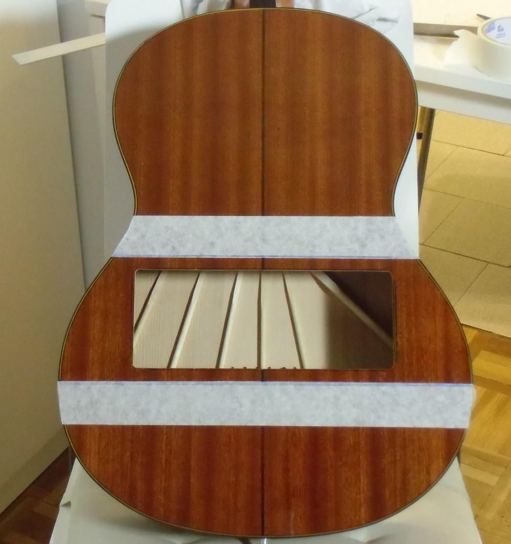
make a hole in the back side of the guitar to access inside the body box
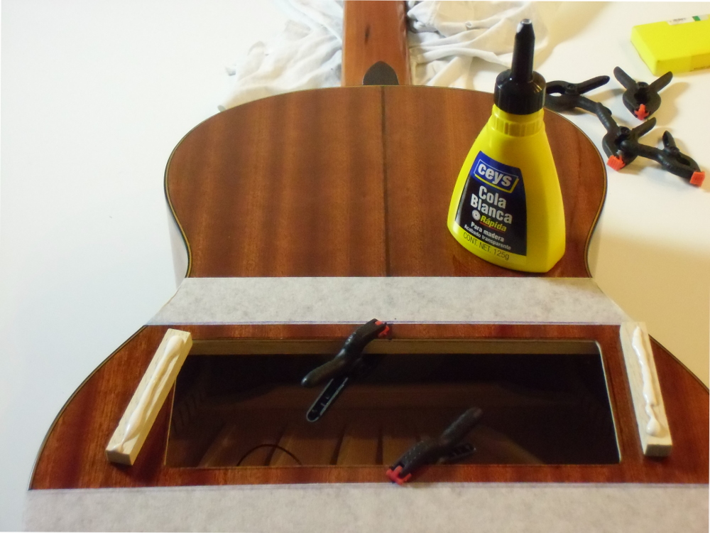
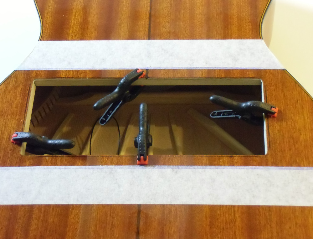
adding a wood strip around the inner side of the hole to screw the cover on it
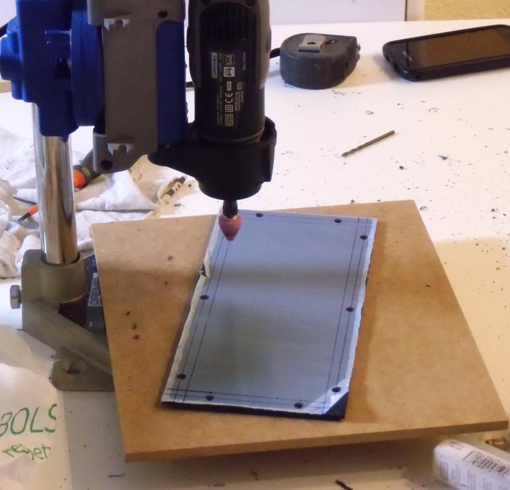
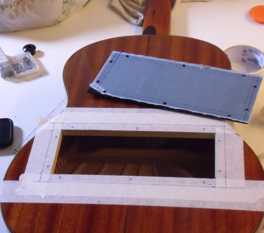
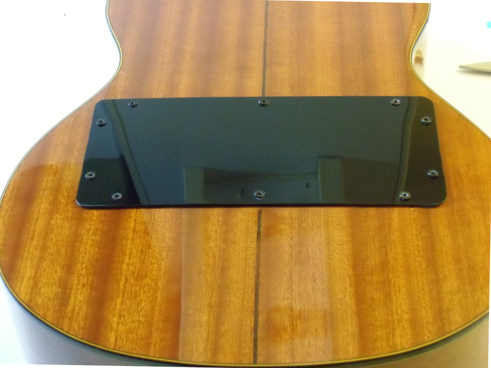
creating and placing the back cover
I also did two small circular holes in the lower right side of the guitar for the 13-pin and the jack connectors. I added another "polycril" small black beautifying plate over the holes and another aluminium plate in the inner side ( inside the guitar box ) to reinforce that part of the guitar body and avoid breaking the wood with undesired blows over the jack or the male 13 pin connectors.
Then installed the two electronic boards and the battery holder inside the guitar box. I glued a small wooden rectangular piece inside the guitar box and screwed one of the electronic boards on it. The other board didn't need to be fixed, because it had the 13 pins connectors soldered on it and got fixed inside the guitar box once I screwed that connector to the guitar while playing.

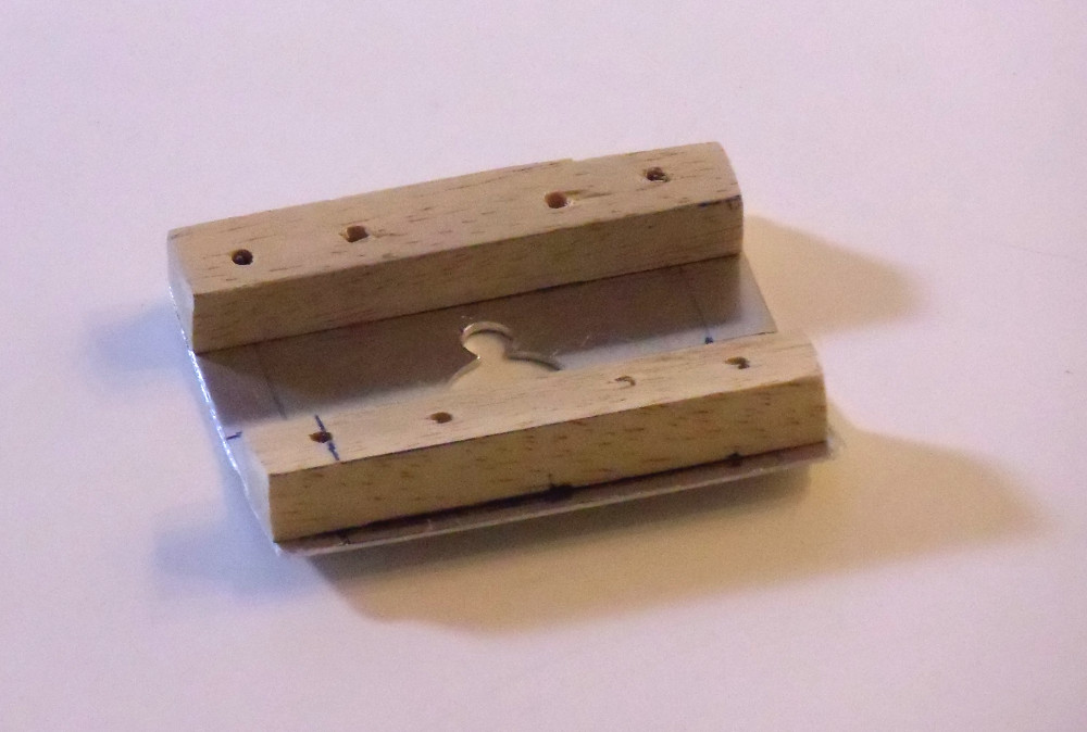
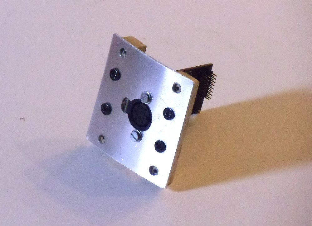
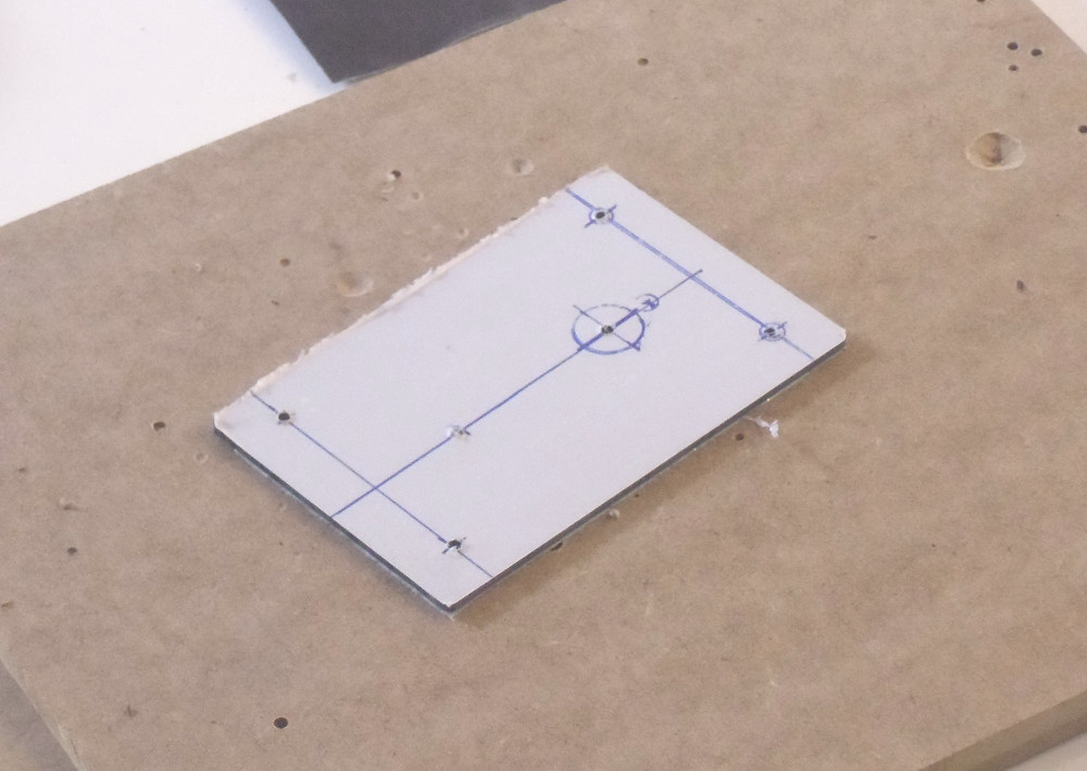
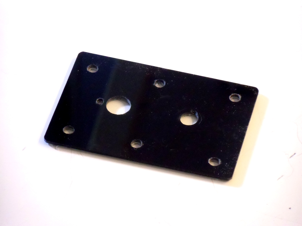
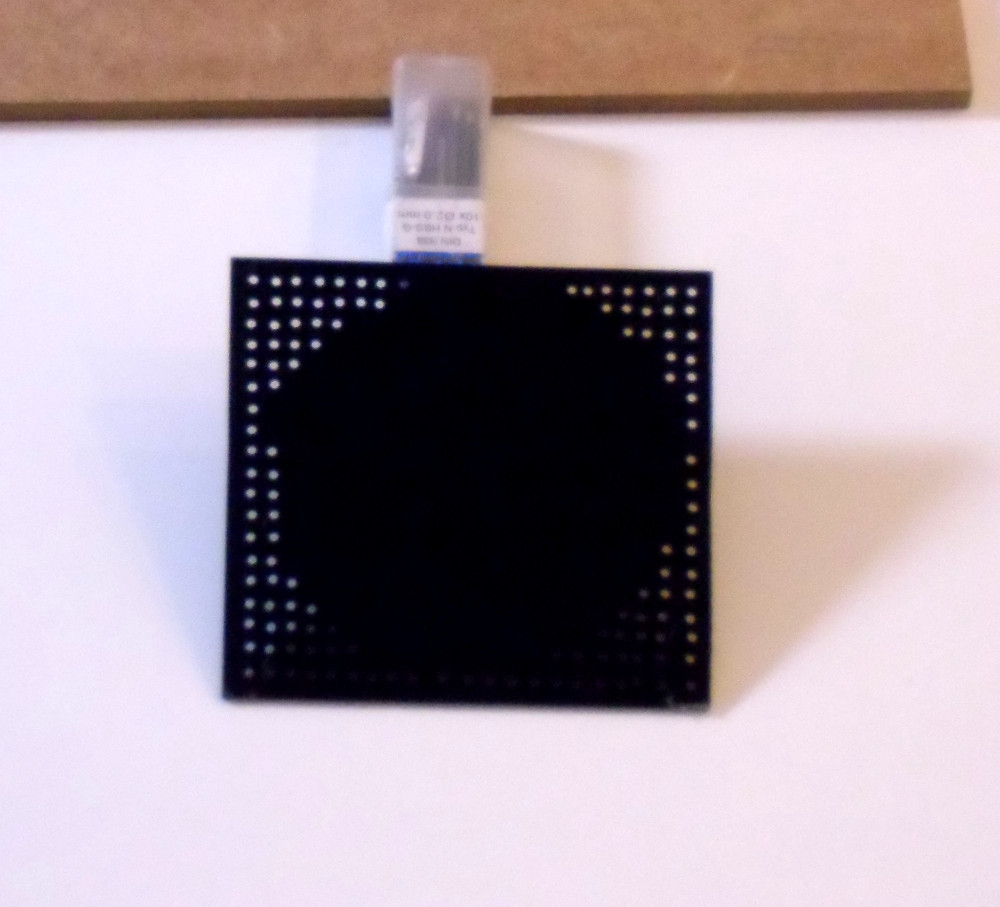
the pickup kit did not include the metal mounting plate so I had to make it by myself
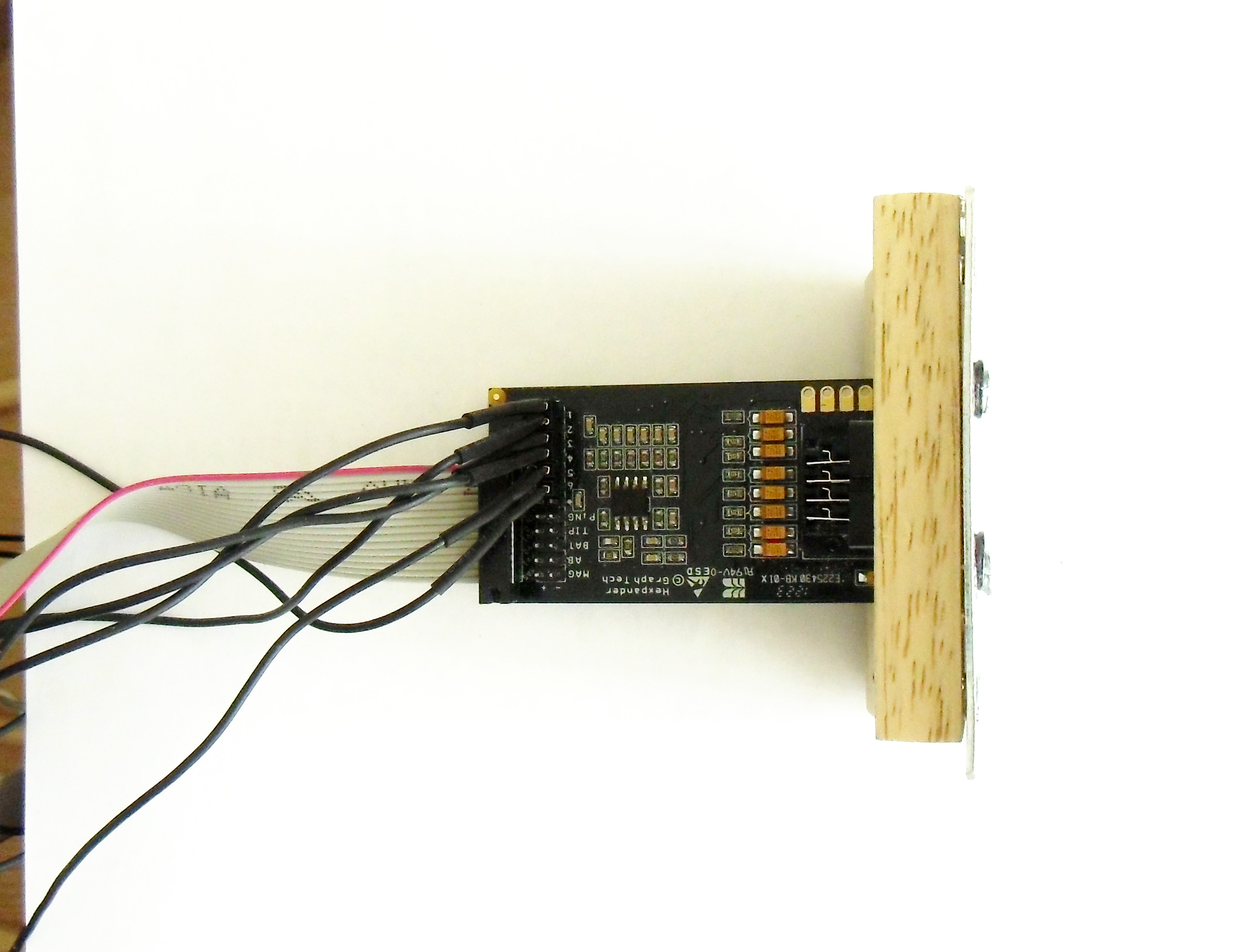
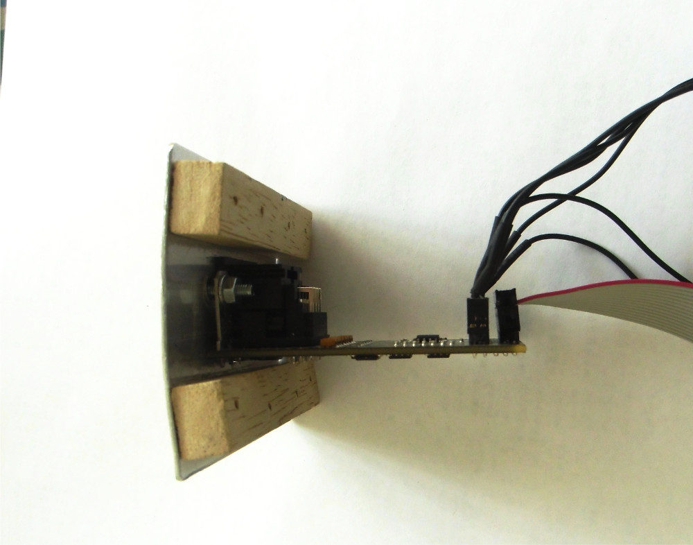
the 13 pin connector adapter board on the mounting plate

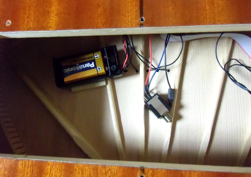
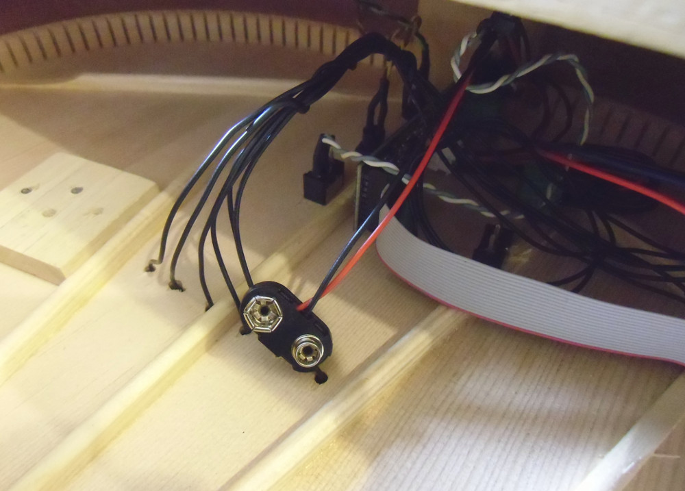
the battery holder and the support for it
Something that surprised me is the poor quality of the battery holder and the jack connector that came with the kit. Despite the other components of the kit were of good quality It didn't happen the same with these two, and I had to buy new good quality replacements for them. The battery holder that came with the kit was very simple and nearly impossible to fix inside the guitar box, and the jack connector thread didn't screw properly.
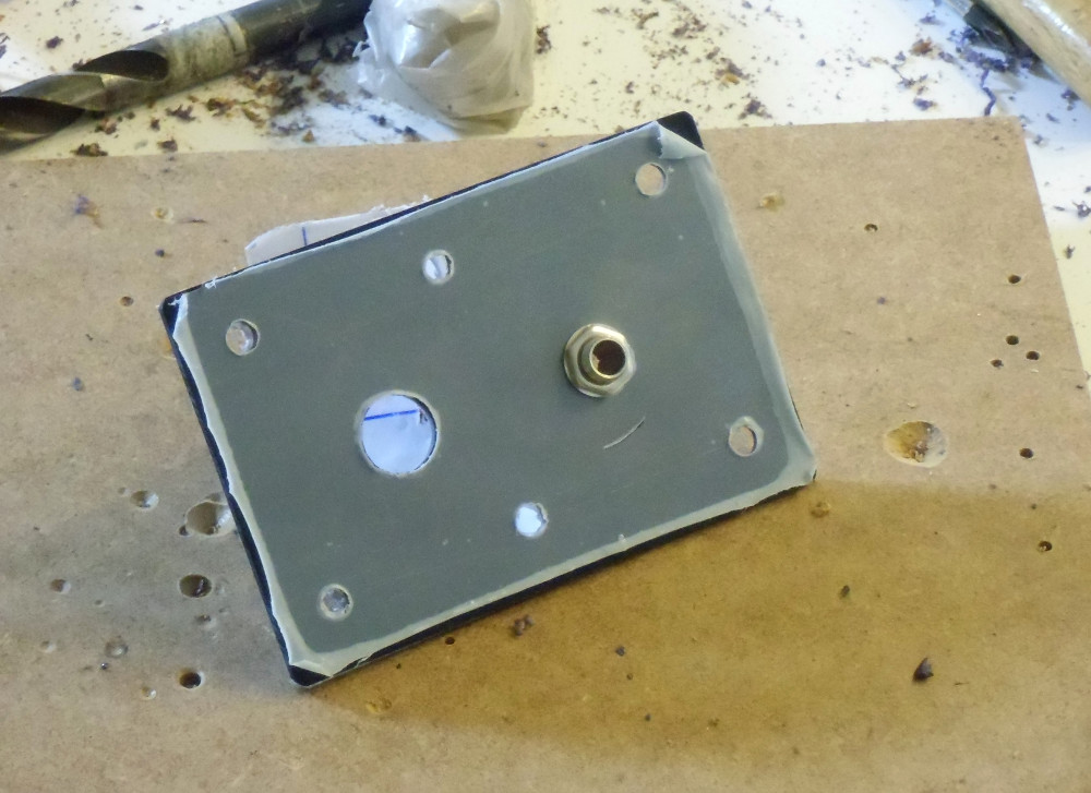
external plate for the 13 pin connector and the audio mono jack
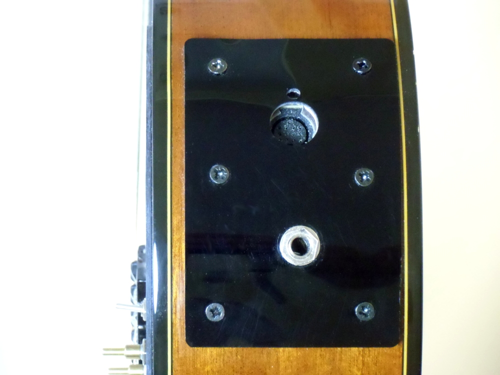

the connectors external plate placed on the guitar
Once I had mounted the electronic boards and the sensors, I placed the strings again on the guitar and tested that everything was OK. After solving a couple of connection issues I checked that all the system was working properly. I tested the 13 pins cable with my Roland GR-55 guitar synth, and the jack cable with my standard Roland Cube amplifier and fortunately everything worked as expected.
As I explained before, the goal of the guitar was capturing the vibrations of the strings to send them to a sound processor or an amplifier, so the resonance of the guitar box is useless for that purpose. For that reason I muted the resonance of the box by placing acoustic foam of different densities inside of the guitar box. This acoustic foam is used to absorb most part of the harmonics produced by this part of the guitar. It also served to decrease the acoustic volume of the instrument, something interesting if we want to play the instrument without disturbing the neighbours. But before placing the foam inside the guitar I had to close the guitar sound hole with a cover to avoid the foam goes out from it.

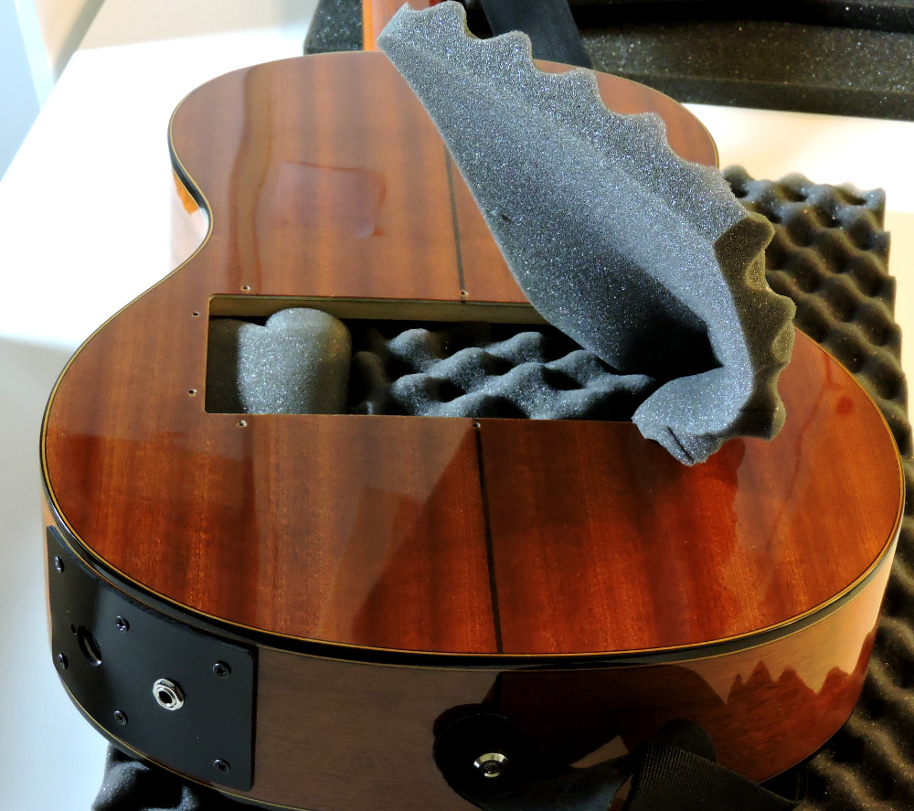
the sound hole cover and the acoustic foam to mute the guitar body resonance

foam placed inside the guitar to mute resonance